1. Create a Polygon Cube and switch to the top panel.

2. Hold right click button and select the vertices in the middle column. Press r to for scale tool.

3. Set the Absolute Values display to Relative Transform. By scaling the vertices, enter 2.9 in the X Axis window.

4. Region-select the vertices in the center of the box width-wise. Scale the vertices by entering 2.92 in the Z-axis window.

5. Change to perspective view and hold right click and select Face. Choose the top face in the center of the box. Select Extrude Settings under the Edit Mesh option in the hotbox menu and reset settings. Apply and Close.

6. Move the manipulator down a little bit on the Z axis. Change the values of Local Translate Z to -29.5. The result is as shown below.

7. Select the face in the corner of each top section, depth and width. Press g to to repeat the extrude command. Move the manipulator up a little bit on the Z axis and set Local Translate Z to 0.2. Press q and change the Local Translate Z again to 17.

8. Select the center faces on the top of the end flaps.Press r for the scale tool. Scale the end flaps a short distance away from the side flaps. Hold right click and choose vertex.


9. Select the vertices on the top of one side flap.

10. Press down arrow to move the vertices down. Add the top vertices to the selection.


11. Press e for the rotate tool and press the insert key. Use the manipulator to move the pivot point near the lower selected vertices on the outside of the box.

12. Press the insert key again to return the manipulator to normal mode. Rotate the flaps out a little bit.


13. Hold right click and select Edge. Go to Edit Mesh and select Insert Edge Tool.

14. Slide the loop near one end of the box – about a quarter of the way along the length – and release the mouse. Continue to add divisions to the length, splitting the faces into 4 sections. They do not need to be evenly spaced.


15. Under Select on the hotbox menu, select Select Edge Ring Tool.

16. Choose the edges you want to bevel later on.


17. Under Edit Mesh in the hotbox menu, change Width and Segments to 1.


18. Hold right click and select Vertex. Select the vertices at an inner edge loop on the top of a side flap.

19. Double-click on the Move Tool icon on the Toolbox to bring up the Tool Settings dialog. Under Move Settings, choose the Set to Face button.

20. Click on the top face of the side flap where the vertices are selected. Move the vertices along the X axis a short distance to create a bend in the edge of the flap. Repeat the process on the opposite flap edge.


21. Go to Mesh in the hotbox menu and select Smooth Settings. Set division levels to 2 and Continuity to .2.

22. On the Status Line, switch the Menu Set to Animation. On the Menu Bar, choose Create Deformers > Nonlinear > Wave.

23. Press r to choose the Scale Tool. Scale the deformer along the X axis to fit the width of the box. In the Channel Box under INPUTS, set Amplitude to .01 and Wavelength to 2. Under wave1Handle set Rotate X and Y to 90.

24. On the Menu Bar, choose Create Deformers > Nonlinear > Wave. Scale the deformer along the X axis to fit the width of the box. In the Channel Box under INPUTS, set Amplitude to .01 and Wavelength to 2. Under wave1Handle set Rotate X and Z to 90.


25. On the Menu Bar, choose Window > Outliner. Hold down the MMB and drag wave1Handle over Box_open. Repeat the process to link wave2Handle to the box.
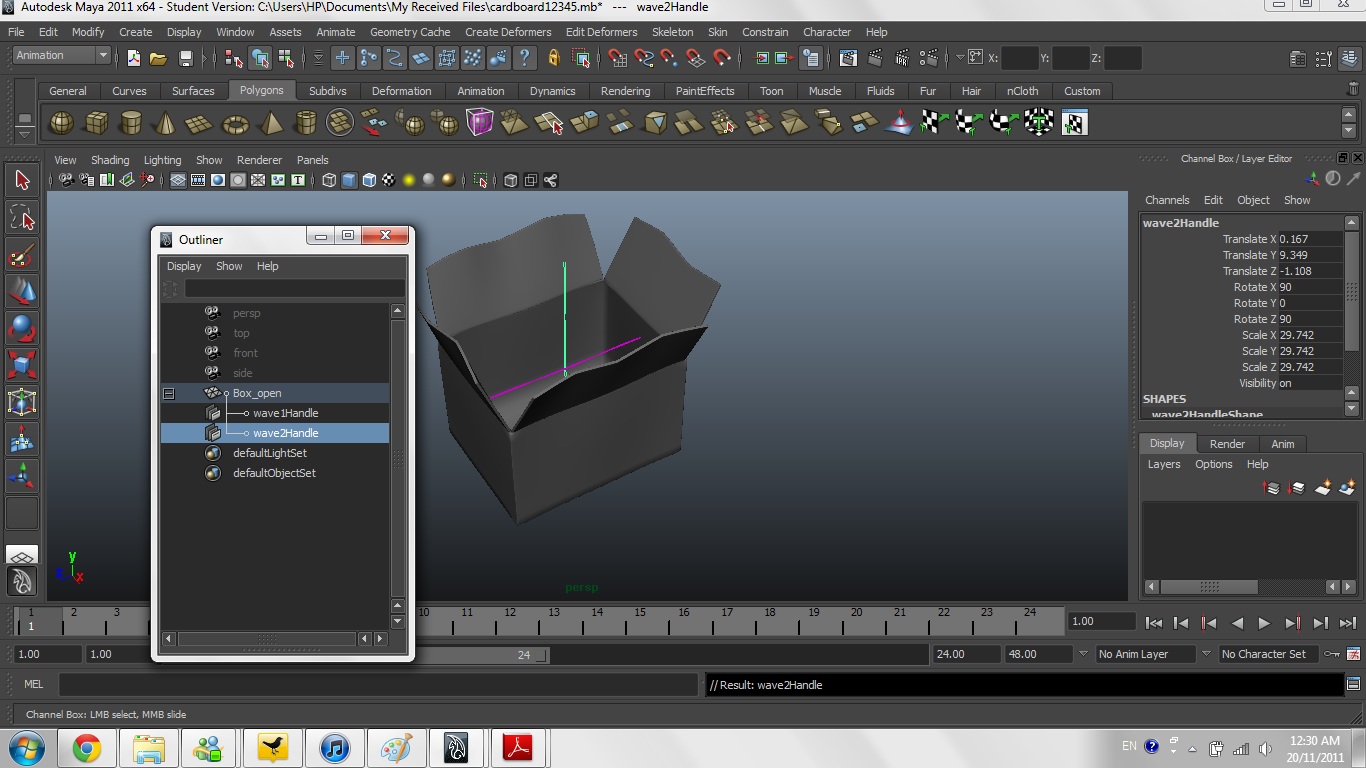
26. The cardboard box is done! ^_^

Reflection:
It took me about 3-4 days to finish this. I could have finished it in one day even though how difficult it is, but due to the homework load, it's very difficult to finish this cardboard modelling in one day. It's instructions are not clear and I had to ask my classmates about it. I hope teachers could reduce the workload! (thanks!) There's a part where i need to bevel the flaps and I got stuck at there and nearly gave up on this modeling. (but I did not!) I could not bevel the flaps because the arrows in the pdf files were unclear. (eg, the small edges at the corner, there are so many! But the pdf file just shows arrow pointing at the corner.) I tried different ways of selecting the edges, but I just could not bevel; it remains the same. After so many tries and helps from my classmates, I managed to finish the beveling and moved on to complete my cardboard modeling.


